Linkages (Part II) - Old Wine in New Bottles Chain and polygonal linkages
2. Chain and polygonal linkages
Here we will be concerned with linkages which are confined to the plane. The diagram below shows two linkages. The first, viewed as a graph, takes the form of a path while the second takes the form of a planar polygon. Another name for a path linkage is a chain.
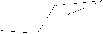

Since neither of these linkages is rigid, one can find different positions or configurations for them in the plane. These different configurations or positions for the linkage reflect the fact that the angles between the consecutive links of the linkage can change without changing the lengths of the links involved. Note that what will change is the distance between one or more pairs of vertices of the linkage which are not joined by edges of the linkage. You should make physical models of these two linkages (use your creativity to do so, but one crude way of doing it is to cut straws of different lengths, and run a string through the straws). Alternatively, you may want to try experiments using software such as Cabri-geometrie, Geometer's Sketchpad, or Cinderella. If one keeps the lengths of the segments fixed and moves the linkage around, certain issues quickly arise. As you move the physical linkage, say, by pushing on a vertex (where two bars meet), sometimes you may push some of the links over the others. This is done in physical space by lifting some pieces of the linkage over other pieces. This means that the motion is not really carried out in the plane. If we idealize to a mathematical situation we can imagine thinking about linkages where the bars can penetrate one another without penalty (thus, one stays confined to the plane) or we can require that bars can touch each other but not penetrate each other.
For example, imagine that your job is to straighten out the linkage below so that its bars lie along a straight line segment whose length is the sum of the lengths of the links in the linkage:
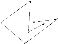
It is clear that if one allows links to pass through others, this is a pretty simple job. For this particular linkage, it is also easy to see a strategy to move the links so that they never penetrate each other but in the end will move to lie along a straight line. Can you see how to prove that if one starts with any plane path linkage, it can be straightened? However, if you have a very complicated plane path linkage and you are not allowed to have interpenetration of links, it's not so clear that every linkage can be straightened. What would be your guess? Can you see a way of straightening the path linkage below by pushing on the vertices and staying in the plane without interpenetration of the links?
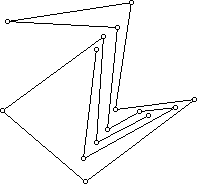
It would be a lot easier if interpenetration were allowed!
Related to the issue of straightening a planar path linkage is the question: If L1 and L2 are two different configurations (positions) of the same linkage in the plane, can one move L1 into L2 while staying in the plane? One way to show that this would be possible would be to move L1 to a straight linkage and L2 to a straight linkage. Now one moves one straight linkage to the other. If this is possible according to the rules, one can move L1 to L2. One can transform two positions of the same linkage in either the non-colliding or collisions-allowed mode. It may be possible to straighten a chain linkage but not without intersecting another nearby positioning of the same linkage. It is common also to consider this problem under the assumption that there may be obstacles that have to be avoided in transforming one configuration to another. Intuitively, this is a very simplified version of what a plane robot arm must do. It must move around in the plane workspace while avoiding various obstacles.
It turns out that while some people thought any path linkage could be straightened in the plane, others thought that a complicated example would be found for which straightening was impossible. For about 30 years researchers were unsure of the answer.
In addition to the question of straightening a path linkage, there is the related question: Is it possible to take a simple plane polygon (one where the sides do not intersect one another) and move it while staying in the plane to have the shape of a convex polygon (one in which a line segment connecting any two points on or inside the polygon, remains on or inside the polygon)? Again we can see that there are two versions of this problem: one where one is not allowed to have the polygon pass through itself at some intermediate stage during the transformation from a non-convex polygon to a convex one and the other where this is allowed.
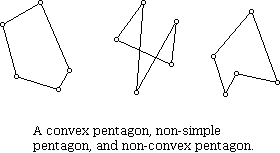
Try out your intuition in each of these two realms. Can any simple non-convex polygonal linkage be transformed into a convex polygonal version of the linkage? Like the case of straightening a plane path linkage, the convexifying of a plane simple polygon is much easier to treat when collisions (that is, interior penetration of edges) are allowed. Do you think any plane simple polygon can be convexified without edges interpenetrating during the motion?
Suppose we are given a linkage where the underlying graph is a plane polygon. In transforming the polygon into other polygons which preserve the lengths of the links we can use familiar transformations such as translations, rotations, or reflections. While the lengths of the links between the vertices are preserved, the distances between other pairs of vertices may not be preserved. The diagram below shows the consequences of taking a pentagon and transforming it so that the lengths of the edges are preserved but the distances between some of the vertices that are not joined by edges are transformed.
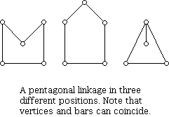
The pentagon is not rigid, so this can be carried out. We are so accustomed to working with rigid motions or isometries that many of the subtle aspects of how to capture what it means for a linkage to be rigid are hard to comprehend. In the figure above, there are 5 points which determine 10 distances, but only 5 of these distances are specified by the bar lengths. Furthermore, the distinction between rigid motions and isometries also comes into play here. Consider the two shapes below:
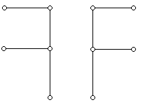
These two shapes can be transformed one into the other by an isometry (in this case, a reflection) but not by a rigid motion. The distinction is that to physically move the letter on the left to superimpose it on to the letter on the right requires that one lift the shape out of the plane; one can not move the shape on the left to the shape on the right while confined to the plane! Also if one considers a scalene triangle (one whose sides all have different lengths), which a bit of experimentation can show is a rigid figure in the plane, you can not transform it by a rigid motion into a mirror image of that triangle. To put this result in perspective, remember that it is not the case that if one has sticks of any lengths whatsoever, one can form a polygon. For example, sticks of length 4, 6, 14 will not form a triangle. Can you find for yourself the simple condition that serves as the necessary and sufficient condition that a collection of sticks can form a plane simple polygon? On the other hand, it's not difficult to see how for some polygons one can transform these polygons into their mirror images. Look at the polygons below. Do you think the linkage on the left can be transformed, in the plane, into its mirror image on the right?
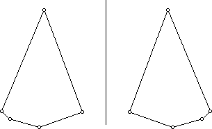
A very appealing theorem of William Lenhart and Sue Whitesides gives the answer:
Any position of a plane polygonal linkage can be transformed into its mirror image if and only if the lengths of the second and third longest links add to at most half the sum of the lengths of all the links.
For example, if the links (in order of size) are 8, 6, 5, 3, 3, 3, the sum of the second and third longest links is 11 which is less then 14, half the sum of the lengths of all the links. Thus, a polygon with these link lengths can be transformed into its mirror image. Perhaps surprisingly, it's not the order of the lengths of the links in the polygon that matter, it's only the lengths themselves. (For the figures above, the link lengths are 2.12, 2.11, 0.91, 0.61 and 0.23. Thus, the transformation is not possible. Notice how close the sum of the second and third lengths is to half the sum of all the lengths - an indication of the value of theorems that provide precise answers!)
- Introduction
- Chain and polygonal linkages
- Breakthrough
- Further steps
- Folding rulers
- References


