Basic ideas
3. Basic ideas
A good way to begin any mathematical investigation is to consider a simple example first. The simplest linkage of all consists of a single rod of length r, whose ends will be denoted A1 and A2. It is convenient to use the language of graph theory in discussions of linkages and refer to the endpoints of the rods as vertices. If we pin down one end of the rod, say the end at A1, then as we rotate the rod about A1 the other end of the rod A2 will trace a circle. It is convenient in cases such as this to think of there being a pen at one location on a linkage, and as the linkage moves to try to figure out what the curve is that is traced by the end of the linkage. In the case here, the point A2 will trace a complete circle of radius r. We can also imagine that a pen is located at a point in the interior of the segment from A1 to A2 and ask what curve the pen will trace. In the simple situation here, we would see a circle.
Notice that if we think of having a single link arm where the point A2 has a device attached which can do work exactly at A2, then the only points where work can be accomplished are the points of the circle centered at A1. Not surprisingly, if we are interested in the points that are reachable by adjusting the angles between the links of a linkage, we need more than one link to be able to reach more than a very restricted collection of points.
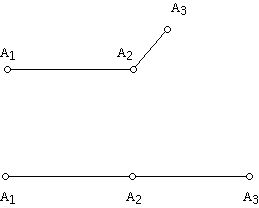
What happens if one uses two bars? There are two cases: the bars can have equal length or different lengths.
The two linkages above with two bars illustrate the situation. In this case we can consider the consequences of pinning one of the two vertices and seeing what happens as we move the linkage around, or we can pin two of the vertices and move the other vertex and edge around. If we pin, say, A1 and A2, then we can move the vertex A3 around. Unlike the earlier situation where we rotated a link around a fixed pinned point, in this case the situation is subtly different. The problem is that as we rotate the link around 180 degrees about A2 we hit the link between A1 and A2. We have to make some assumption about whether we can continue to rotate the link between A2 and A3 further, which would be physically impossible but mathematically possible. Not surprisingly, taking into account the physical restriction makes the analysis much harder. For now we will allow links to be positioned on top of one another or to self-intersect. Thus, in this situation we get that A3 will generate a circle about A2 of radius r. You may also wish to think about the situation where we pin points A1 and A3. Can you figure out if there is any motion possible for the resulting system?
If we do not fix A1 and A2 but only pin A1 then we can rotate the link between A1 and A2 and the link between A2 and A3 independently. Can you figure out what collection of points are reachable with these constraints? How does the answer depend on the lengths of the two links involved?
In thinking about these issues one can introduce a convention about the way to measure the angles between the segments that make up a linkage. If one has a planar linkage, with one end pinned, let (x, y) denote the coordinates of the point P at the other end of the linkage (this end point is often called the end effecter). It is not difficult to determine the x and y coordinates of P if one knows the angles between the links. However, given a point that potentially might be reached using the linkage (i.e. given the (x, y) coordinates of the point) it is not so easy to see how to set the angles which will put the linkage's end at the point with these coordinates or be able to specify that the point is unreachable. Furthermore, it is not difficult to see that two different positions of the links can put the end effecter of the linkage in the same place.
You can easily verify that a linkage of two segments pinned at A can reach the position C for the end effecter with two different sets of angles.
If the linkage has n links, one needs n angles to specify the position of the links with respect to each other that gives rise to the coordinates of P, where the end effecter is located. One can think of the angles as specifying a point in n-dimensional space, where points in this space, called the configuration space of the linkage, correspond to the different positions that the linkage can take on. In a general way it is of considerable interest to study the relationship between the parameters of the linkage and its configuration space.
Recent work on planar linkages involves the presence of obstacles in the workspace of the linkage, where you should think of the linkage as a robot arm confined to move in a plane. The idea is that as the robot arm moves it must avoid existing objects in its workspace as attempts are made to use the arm for specific tasks. The obstacles create the possibility that one has positions that the robot arm can not achieve while totally confined to the plane. In other words from the configuration space point of view, the configuration space of the situation is not connected which means that one can not move within the plane between some different positions that the robot arm might be in!
-
Introduction
-
Some history
-
Basic ideas
-
Peaucellier-Lipkin linkage
-
Sneak preview: carpenter's ruler problems
-
References
Welcome to the
Feature Column!
These web essays are designed for those who have already discovered the joys of mathematics as well as for those who may be uncomfortable with mathematics.
Read more . . .
Feature Column at a glance