Fourier Analysis of Ocean Tides III
With JAVA animation by Bill Casselman
Feature Column Archive
2. A conversation in a railway carriage
In 1872 Kelvin was preoccupied with the tidal prediction, and in particular with the problem of summing a large number of harmonic motions with irrationally related frequencies. Here is how the solution came to him, in his own words (Mathematical and Physical Papers, Vol. VI Cambridge 1911, p. 286).
Dramatis Personae. The Author: William Thompson, later (1892) Lord Kelvin. Mr Tower: Beauchamp Tower, an engineer and inventor. His 1883 experiments on lubrication were the basis for the ``Reynolds Equation,'' later treated by Sommerfeld. Mr White: James White of Glascow, ``Philosophical Instrument Maker to the University.''
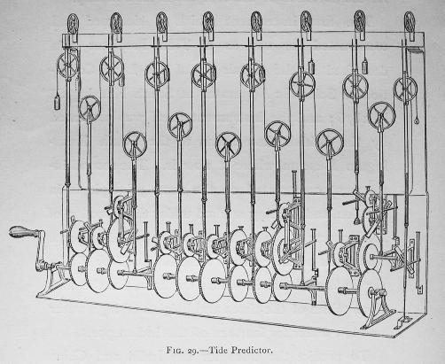
The model was soon succeeded by the First Tide Predicting Machine, which was completed in 1875, and could sum 10 tidal constituents. It was succeeded in turn by a second (about 1880), a third (about 1883) and a ``Fourth British Tide Predictor'' (1910). The machine illustrated here is the third.

Click for larger image
A wire is fixed at the right and passes alternately over and under 15 movable pulleys, after which it suspends a weight (in this image; in practice, an ink bottle with a pen). Each of the movable pulleys is driven in a vertical simple harmonic motion, as follows.
- Turning the crank it drives eleven gear assemblies. The gear ratios are chosen so that the speeds of the output gears in each assembly are uniformly proportional to the speeds of the tidal constituents being summed. (Two of the assemblies, #3 and #9 counting from the left, have two output gears, corresponding to pairs of rationally related constituents; one of them, #11, has three).
- Each output gear drives one of the movable pulleys by an linkage which converts the rotation of the gear into vertical harmonic motion. The linkage attachment to the gear is by an eccentric pin mounted at an adjustable radius. In this way the amplitude of the vertical motion can be set to match the coefficient of the corresponding constituent at the port in question. Likewise the initial angle of each pin can be set so that all the constituents are in the correct phase for the moment the simulation is to start.
- One last wrinkle: the pulleys in the lower row must be set 180 degrees out of phase with those in the upper, because when they go up, the pen goes down. The motion of the pen is then exactly twice the sum of the motions of the pulleys.
The crank also moves a strip of paper horizontally in front of the pen (this is not shown) to record the predicted tidal curve. Image from Kelvin, Mathematical and Physical Papers, Vol. VI, opposite page 304. The planning of the gearing, which gives excellent rational approximations to the astronnomical ratios, was carried out by the mathematician Edward Roberts, who also supervised the construction. |
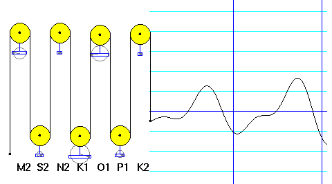
The functioning of this mechanism, and the way in which the various constituents contribute to the tide, are illustrated in a JAVA applet contributed by Bill Casselman of the University of British Columbia.

Click on image to activate applet.
|
Welcome to the
Feature Column!
These web essays are designed for those who have already discovered the joys of mathematics as well as for those who may be uncomfortable with mathematics.
Read more . . .
Feature Column at a glance


