Math and the Sewing Machine
In this column I will explore mathematical aspects of the action of the sewing machine and of the often associated bobbin winder...
 Tony Phillips
Stony Brook University
Email Tony Phillips
Introduction
The sewing machine is one of the marvels of 19th-century mechanical invention. (Mahatma Ghandi is said to have called it "one of the few useful things ever invented.") Unlike the typewriter and the cash register, it can not be displaced by electronics since it manipulates material, not information. In this column I will explore mathematical aspects of the action of the sewing machine and of the often associated bobbin winder: how the lockstitch is topologically possible, and how a cam shaped according to Archimedes' spiral ensures even winding of the thread on long bobbins.
Stitch topology
The most primitive sewing machines used a single thread, and executed a chain stitch:
Chain stitch: at each stitch, a loop of thread is pulled through the loop left by the previous stitch. This animation on YouTube shows how a machine does it.
The chain stitch is topologically unproblematical because the thread is completely unknotted: tugging at the right-hand end in the image above is enough to undo the entire seam. This makes the chain stitch still useful in closing bags of potatoes, dog food or charcoal briquettes, where easy unraveling is an asset. But that feature is clearly undesirable, for example, in clothing.
The first machines that could sew a lock stitch (which will not unravel) were invented in the period between 1830 and 1850. These machines used two threads to sew a seam.
Lockstitch: at each stitch the upper thread links the lower, always in the same direction. If the cloth is removed, the threads can be seen to be evenly twisted, one about the other, with one complete twist per stitch.
At first glance, having a machine execute a lockstitch seems topologically impossible. The machine uses two threads to sew a seam; each thread comes from a spool: the top thread from the spool conspicuously stationed on top of the machine, the bottom thread from the bobbin, hidden inside. How is it possible for the two threads to link, over and over?
The answer is that the bobbin is not attached to the rest of the machine. In early machines the bobbin sits in a bullet-shaped shuttle that passes, at every stitch, through the loop formed in the top thread by the advancing and retreating needle. This can happen because the shuttle floats freely inside the machine. In more modern machines, the bobbin is tucked into a smooth round metal shuttle that stays in one place, although it floats there unsecured. So at each stitch the thread from the top spool can be led completely around the shuttle, picking up the bobbin thread in a twist as it is drawn tight.

Two strategies for executing a lock stitch. Left: "Oscillating (or Vibrating) Shuttle." At every stitch, the shuttle carrying the bobbin (blue thread) passes completely around the loop created by the top (red) thread. Right: "Rotary Shuttle." The bobbin (green thread) is enclosed in a smooth circular shuttle which stays fixed, while at every stitch the top thread (yellow) is drawn completely around it. In either case, for this to be topologically possible, the shuttle must be floating free inside the machine. These two GIF animations are made available through Wikimedia Commons; click on them for details.
Comments?
The Archimedean Spiral in the bobbin winder for oscillating shuttle machines
I learned about this feature from my friend and sometime colleague Enrico Giusti, who mentioned it in a lecture last month at the "Matematica e Cultura" conference in Venice. It is explained as part of an exhibition at The Garden of Archimedes, the mathematics museum he has organized on Via San Bartolo a Cintoia in Florence. The exhibition, due to Franco Conti, is based on the book Oltre il Compasso: la geometria delle curve that Conti and Giusti published in 2000. The bobbin winder thread feeding mechanism is presented on this page of the museum website.
For those unfamiliar with lockstitch sewing machines, each machine tends to have its own specific shape of bobbin, the small spool that nestles inside the shuttle and carries the bottom thread. So the thread scheduled to go on the bottom, for any particular sewing project, needs to be especially wound onto the bobbin. Sewing machines often have a device for this purpose, usually attached to the main column, out of the way of sewing operations.
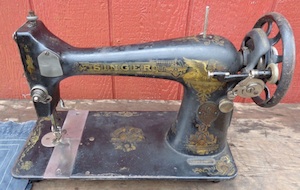

This is a Singer Sphinx Model 27, made in 1910, and recently for sale on Ebay, with the bobbin winder shown close up. The Model 27 was designed with an oscillating shuttle. Image used with permission.
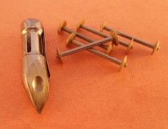
Bobbins for the bullet-shaped ocsillating shuttle had to be narrow and long (about 1.5 inches for those shown here). Image from Ebay, used with permission.
For the short, squat bobbins in rotary shuttles, ensuring that the thread winds to an even depth is usually not a problem; the winders on these machines let the thread even itself out (although one is advised to watch the process and to intervene with one's fingers if necessary). But a long, narrow bobbin like those used in the Model 27 cannot take care of itself: the thread needs to be led back and forth along the bobbin during the winding process. A very simple mechanism could project a rotary motion onto a back-and-forth one, but Conti explains how this would lead to thread piling up near the two ends of the bobbin.

A simple mechanism in which the thread could be led through a point on a rotating circle with diameter the length of the bobbin and then directly down to the bobbin would lead to pile-ups at the ends. In the diagram on the right, the green region would get twice as much thread as the orange region of the same length.
The solution devised by the inventors and perfectioners of machines like the Model 27 is to use a rotating disc as above, but to mount on it a cam shaped like two copies of Archimedes' spiral (in polar coordinates, $r=\theta$ for $0\leq \theta\leq \pi$, and $r=-\theta$ for $-\pi\leq\theta\leq 0$). A lever arm magnifies the range to match the length of the bobbin.

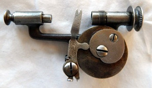
The operation of the bobbin winder on a machine like the Model 27. When the winder is engaged, a rubber tire (missing) rests on the main drive wheel. The bobbin is held in place by the spring-loaded plunger at the left. As the bobbin spins, a screw drive meshes with the teeth on the edge of the flat disc bearing the heart-shaped cam. The thread is led through the notch in the end of the lever-arm, which is held by a spring against the edge of the cam. On the left the angular position of the cam is near $\theta=\pi$ and the thread would be led to the left end of the bobbin. On the right, the cam is approaching $\theta=0$ and the thread windings are moving towards the right end. In between, as the cam rotates, the end of the lever arm moves uniformly (directly proportionally to $\theta$), from one side to the other. Images from the listing of an item recently sold on Ebay, used with permission.
Finally, to see the winder in action, I recommend Lizzie Lenard's tutorial "How to wind a Singer sewing machine long bobbin and load the shuttle the correct way," on YouTube.
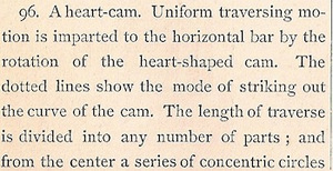
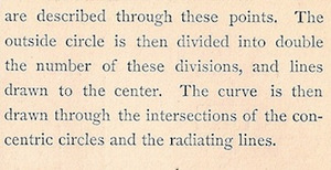
The use of Archimedes' spiral to transform circular motion into uniform linear motion is described in 507 Mechanical Movements by Henry T. Brown (Editor of "The American Artisan"), Brown, Coombs, New York, 1868. The book is now available online with some of the movements animated (not this one). This particular movement is No. 96, illustrated and explained as below. The text gives a simple graphical method for drawing a pair of Archimedes' spirals.
See Elsa Jansson's Finnish translation of this column and Fedor Minorov's Russian translation of this column.
Tony Phillips
Stony Brook University
Email Tony Phillips